
Last year I’ve built a Mendel90 3D printer. Soon I’ve printed an adapter for the Proxxon Micromot 50, so that I could use the printer also for drilling and milling. Drilling was easy, and this weak I gave milling a try and experimented with milling PCBs created with eagle.
For Eagle there exists the cool plugin pcb-gcode, which can create GCode from a board design. The problem is that GCode is not portable and very machine dependent. And the plugin is designed more for professional CNC milling machines in mind, so I was unsure if this could work with my homemade 3D printer / CNC milling machine.
For this reason I’ve created a simulator which I could use to test exported GCode before damaging my machine, tools or PCBs. It turned out that this was quite easy to achieve. First because GCode is so simple to parse and second because I had a cool idea how I could easily implement the milling simulation.
The result of the simulation is a simple PGM image that looks like this:
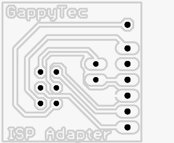
It can be used to quickly view the milling results as a gray image, where the gray value indicates the milling depth (darker means deeper).
The problem is that it is not sufficient to draw some line for the GCode path like it is done e.g. by the Pronterface GUI that I’m using to control my printer, You need to know the dimensions of the milling cutter and where it interacts with the workpart. Sounds complicated, right? The simple solution for this complex problem is voxel space.
Voxel Space
Was used for gaming engines like in the good old Comanche game. Actually this was just a height map, a 2D array where each byte is the height of the voxel which builds the terrain surface. A voxel is a cube (volumetric pixel) that is used to create 3D objects, which is different to the typical 3D game of today which is created using polygons. But enough on 3D games.
It would be possible to create the simulation for PCB etching purely using a heightmap like in Comanche, but I decided to use a real 3D matrix of voxels, so that I can produce all kind of shapes including overhangs. The workpart consists of a voxel space and the milling cutter too, to be able to simulate the interaction of both.
Lets create an example: A PCB with 160mm * 100mm * 1.6mm and a resolution of 0.1mm (voxel width) would require a matrix of 1600x1000x16 voxels which results in 25.600.000 voxels which can be stored in 3.200.000 byte which is 3.125 KB or about 3 MB of RAM. The milling cutter with 3mm diamter and a height of 5mm would require 30x30x50 = 45.000 voxels or 625 byte.
The tool’s voxel space get moved by the GCode, therefor I needed to create a simple GCode parser. The main application converts the units of GCode into voxel space coordinates and then the voxel space implementation computes the difference of workpart - tool, which means clearing the voxel at that position where a voxel in the tool’s voxel space is set. This way the tool can cut into the workpart and removes “material” from it. This is repeated for every new step of the GCode interpreter, which actually only consists of linear moves.
The resulting voxel space of the workpart get’s stored into a portable gray map file, which is easily to produce and can be used to inspect the result or to convert it into other formats using Image Magick.
POVRay Simulation
The gray map file can be created quickly and is all you need to inspect the results of Eagle exported GCode. But of course I wanted to see some nice 3D animation of my simulation. Because 3D programming is a lot of work I decided to simply produce a series of workpart gray map files for all the individual steps and use POVRay to produce nice 3D images, which then get combined into a video using ffmpeg. For workpart gray map is used as an heigh field in POVRay, the tool is written into a density file (.d3f), because it contains overhangs and height fields would not be very useful here. The density file represents the 3D voxel space and is rendered using an isosurface (this was the trickiest part). The final result you can see in animation at the top of this blog.
Rewriting GCode files
While I was writing this blog I was further improving the tool. Meanwhile it can parse multiple GCode files, e.g. etching and drilling. This was used mainly for creating the video above.
The more important improvement is that it can now write new GCode files applying offsets (translations) using XYZ coordinates. This way you can “etch” the same PCB at different locations. You could also just change the coordinate system of the printer using the G92 command, but I found it better to keep the coordinates after Homing and apply the coordinate changes using my gcodesim tool.
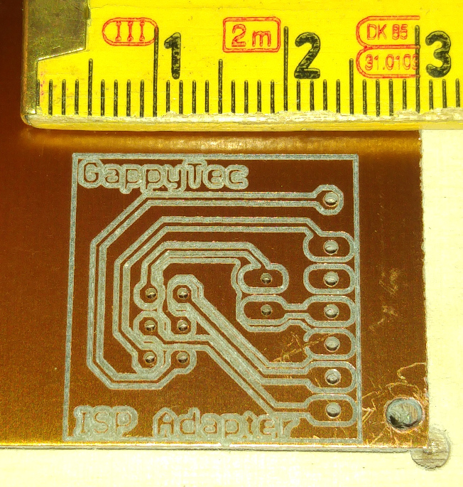
The following images shows one of the first real PCBs, created with -5mm translation on X axis to avoid a problem with the drill hole for mounting th e PCB on my printer table.
Future improvements
This improvements would be possible, but I don’t promise anything ;-)
- performance improvement of voxel space difference by computing this word wise instead of bit wise
- trying to implement it using a height field instead of a full voxel space
Coming next
If you read until here you probably want to try the same. Cool. In my next blog I will explain how to configure Marlin firmware to achieve the following:
- move to negative Z coordinates for milling/drilling
- Z Homing using your drill/mill tool (electrical contact)
- Auto bed leveling using the drill/mill tool
Download
You can get the sources on Github
Comments
comments powered by Disqus